1S Li-Po battery charger
One day I hope to design a product with quality of a commercial product. I do not feel I can go through the entire process by myself. While I might never be able to do that, I still want to close as much of that gap as possible.
This time the exercise was to design a PCB that can charge a 1S Li-Po battery. The design is not a product of my lacking, electronics knowledge. It’s a modified design of the Particle Xenon board. Unfortunately, Particle doesn’t produce these boards anymore. I managed to buy two of them some time ago. I find those great for BLE prototyping.
While trying to understand their battery charging circuit, I’ve decided to ask for help on r/Electronics subreddit. One of the commenters helped me to understand the schematic and also simplified it. Thank you kind soul! I have proceeded to implement that simplified design in KiCad.
I’ll use this short paragraph to appreciate KiCad. It’s an incredible, open-source tool. It might be missing some features that other programs of this type have but the benefits of a well maintained, open-source tool are way more important. Considering that I learn PCB design as I go, I don’t see myself missing those features anytime soon. Few things I love about KiCad: everything is stored in text files (I can change the size of the silk screen labels with a quick edit, using my text editor; the project can use Git for version control), it has a great keyboard navigation, it’s not bloated, it’s performant, free and I can easily install it on any machine I own.
I knew I’ll hand solder this PCB but at the same time I chose some SMD footprints I’ve never used before. The biggest mistake was the 0402 SMD footprint for an LED. That’s the only feature that doesn’t work correctly - the LED doesn’t light up. Very likely I just soldered it backwards.
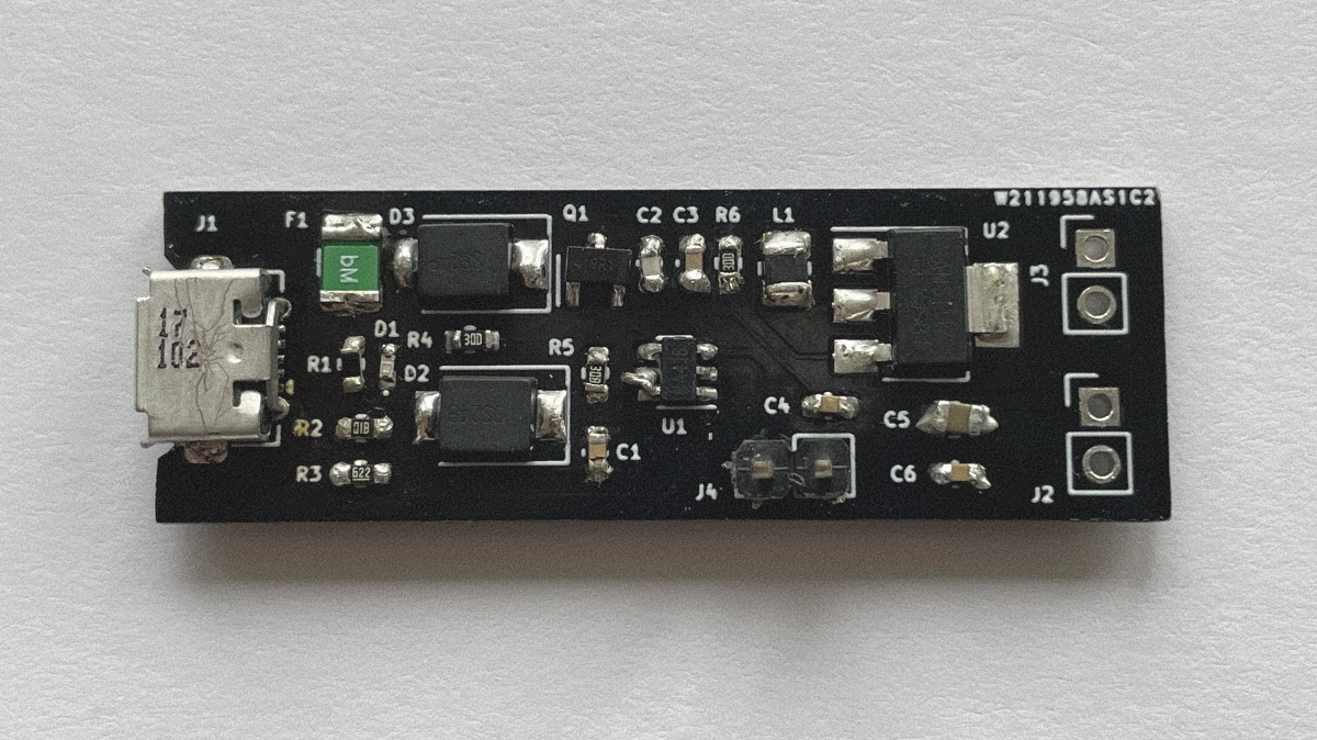
Testing of the board showed that the board works! It outputs the 3.3V when connected to the USB and it charges the battery. On a close to fully charged battery it outputs 3.2V… which… isn’t great. The culprit is the 3.3V LDO voltage regulator. Those regulators are good at regulating the voltage if the delta between input and output voltage is low. For a 1S Li-Po, with max voltage of 4.2V, this delta is just 0.9V. That’s not much really. The LDO I’m using is the AMS1117 and ,according to its datasheet, its dropout voltage is 1V - difference between input and output voltage that guarantees this LDO’s output voltage of 3.3V.
I was curious enough to actually test this LDO. I hooked up a bench power supply to its input and a multimeter to its output. I have written down the measurements while increasing the input voltage , from 3V, by 0.1V, to 5.1V. The LDO outputs 3.3V when the input voltage is higher than 4.3V. That’s a difference of 1V between input and output voltage.
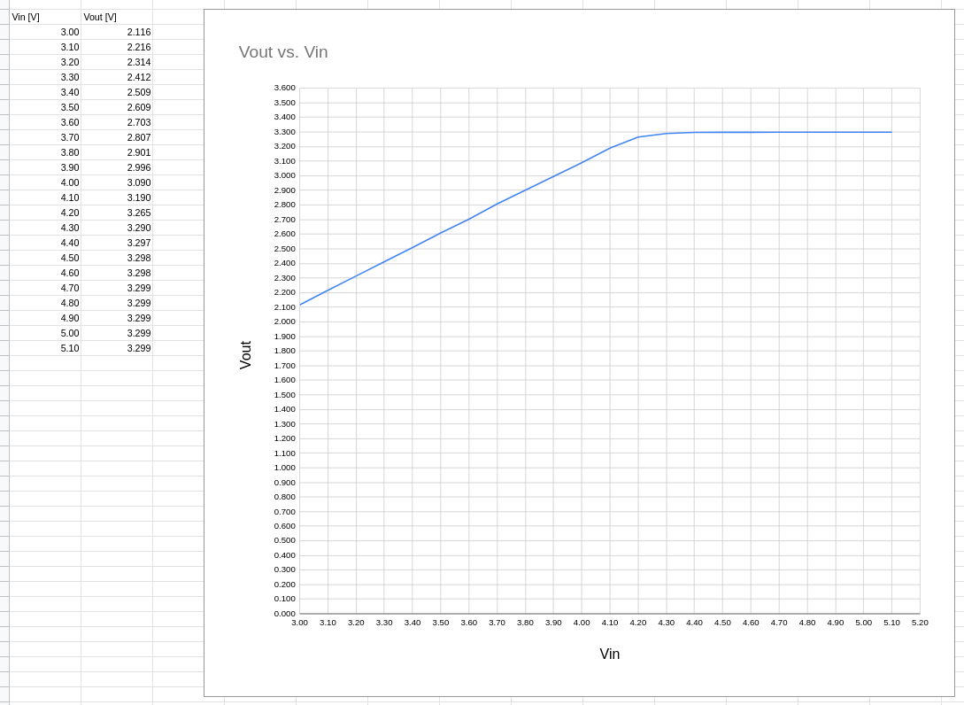
A 1S Li-Po battery drops to 3.6V when it’s close to being fully depleted. With this LDO that would give an output voltage of 2.7V. I don’t want to blow your mind here, but… that’s less than the expected 3.3V.

Who’s to say? Who’s to say if I even can read?
The board that inspired this project used the XC9258A33CER DC DC switching regulator.
Lessons learned:
- carefully read datasheets of the components you choose (it’s embarrassing to write this down)
- you can measure things without test points, but why would you, if you can add some test points for free
- always print the PCB layout, on paper, to check the size of the PCB and the footprints
- soldering 0402 SMD footprint by hand is absolutely doable, for me, but I’ll never torture myself this way again
- it might be time to start using stencils and soldering paste
- picking components and sourcing them is PITA
- it’ll always bother me that the minimum order of the PCB boards is 5 pieces (I need 3D printing level of making PCBs)
While it’s hard to call the result a success, I have learned a few things, and that will definitely make my next designs better.