Bluetooth Graphics Controller
Process <

Summer isn’t the best time to push personal projects, but I’m doing my best to push this one. I had to take a step back though. The BLE controller still doesn’t work with Windows. Even though it’s fun to learn about BLE this project isn’t about protocols. It’s about exploring a possibility of creating a controller designed for CG artists. Trying to debug BLE problems is exhausting and it kills any excitement for this project. I needed to bring to focus back on the main goal of this project. I did that by going back to USB protocol.
This project of mine used the Bluepill board to implement a HID controller with Wii Nunchuk. That meant that a lot of problems I’ve already solved. I’ve spent several days to create a project which will act as a generic USB HID Keyboard. I’ve improved the original Wii Nunchuk project a bit. I’ve also found some glaring mistakes and bugs which I’ve fixed in the new project. It was also interesting to see how my style of writing code changed since the time I’ve worked on the Wii Nunchuk project.
Ok, ok, ok, the important part: I’m using the Bluepill acting as a USB HID keyboard for now. I’ll come back to BLE in the future because I want this controller to be wireless. I’m focused on prototyping the actual hardware right now.
The first prototype was an eyeballed sketch made in ZBrush, retopoed and tweaked in Blender and printed on my Ender 3 3D printer. I’ve used some plasteline to tweak the shape and attach the buttons.
That inspired me to design the shape of the second prototype using plasteline. This process was incredibly fun! Digital design + 3D printing is so slow in comparison. The immediate feedback, real world scale and precision of my own hands allow me to explore the design with incredible ease.
I’m very proficient with Blender and ZBrush and I enjoy using those tools a lot. They allow you to explore for free. There is no material cost and any mistake can be fixed with Undo. For a hardware project, like this one, the immediate feedback itself is worth getting your hands dirty.
Below you can see the results. They are a bit dirty, because plasteline gathers all the dust and small crap like pieces of clothing fibers. The core has been made with a baking aluminium foil. That’s usually what sculptors use to save material and reduce the weight of the piece.
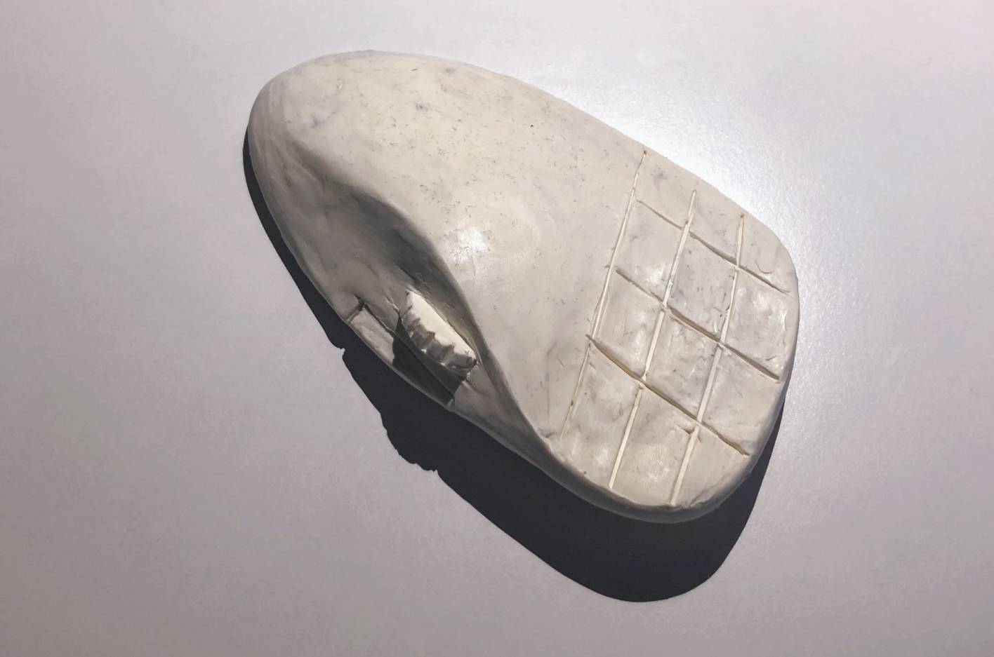
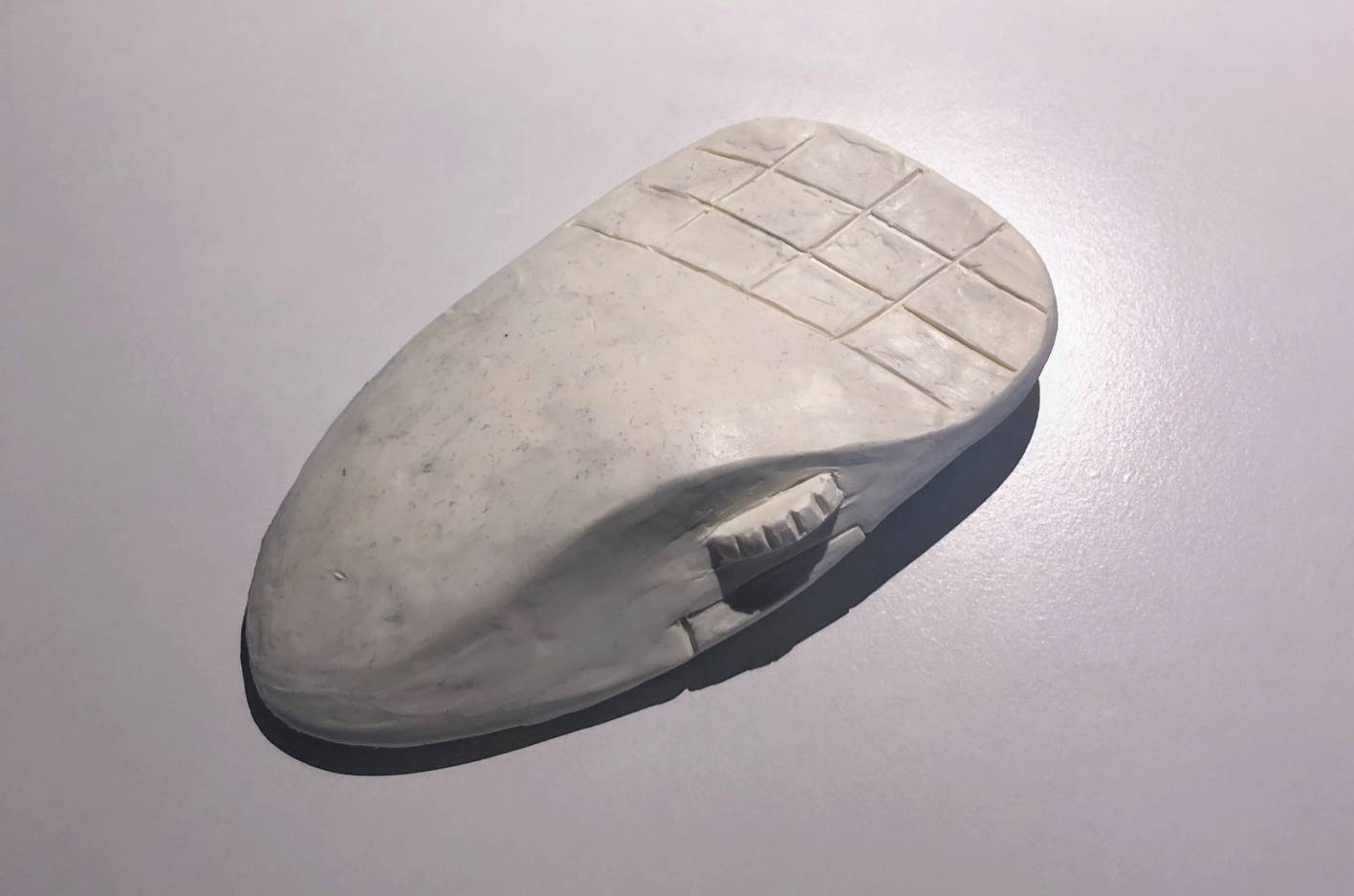
If something stuck out too much I’ve just scooped out some material with a knife. If I needed more volume I just added more plasteline and spreaded it out with my fingers. I was surprised how little material you actually need to make something like this.
I have took photos of this prototype in order to transfer it into a 3D model via photogrammetry. I’ve already generated the 3D model with Agisoft Photoscan and am currently working on retopologizing it in Blender. When I’m happy with the result I’ll simply 3D print it. If you want to do something similar I suggest putting something that’s easily measurable close to the photographed object. That way you’ll be able to easily keep the real world scale of the object, in your 3D modelling app.
I’ve also changed my approach to how the entire prototype is wired. No surprise: prototype needs flexibility. I like my prototypes to be sturdy and not fall apart when moved but soldering each wire is a bit much. With the help of IDC connectors I feel I can strike the right balance.
I know that this log still haven’t communicate the idea behind this project. I’ve finally managed to build a prototype which shows what I’m trying to achieve. I wanted the first demo to be about working with ZBrush but unfortunately Windows doesn’t recognize the device as a HID device. I think that’s because it doesn’t receive the HID descriptor properly. Android and iOS devices work well with the current firmware.
After building the first prototype I wanted to reward myself with trying to use this device. The only art app I’m using on Android or iOS is Procreate. I’ve quickly googled hotkeys that Procreate supports and flashed a firmware with a keymap that uses those buttons. Video below shows the result. It’s super far from what I want it to be but it’s very rewarding to see it working after a lot of time spent trying to fix the SDK… Yes, the SDK is crap.
I’ve ordered 10 Kailh, low profile, brown switches… which is way less then I needed. Don’t know what I was thinking. At least now I know I don’t want to go for the brown ones. I like tactile feel.
I’ve read a bit about how keyboards check the states of the switches. A great explanation of how it’s done can be found here. The specific way keyboards read the state of the buttons makes it easier to reduce the number of input pins that need to be used.
For the layout, I’ve shown in the previous post, I’d need 15 pins to read the state of each of the keys. The approach used by keyboards reduces that number to 8. In the image below each row and column needs to be connected to a pin.
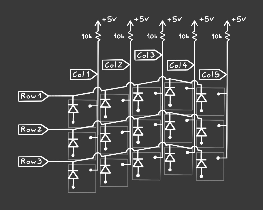
The problem of this solution is that the code needs to be a bit more complex. That’s because reading the state is done row by row. This article explains the process pretty well.
At this stage of this project I think I’ll stay with one pin, one key approach. I’ve got only 10 switches… I’ve also 3D printed some basic shapes that I can use as a base of the controller. With the final print, a bit of plasteline and a bit of soldering I can build a first half prototype.
The controller (unfortunately) has to provide a lot of functionality the keyboard does. It also shouldn’t be making input complex, only because there is not enough keys. At the same time: less is always better. Just think about how many hotkeys you actually use. I’ll strive for reducing the key count but the final count will be a result of testing the prototypes.
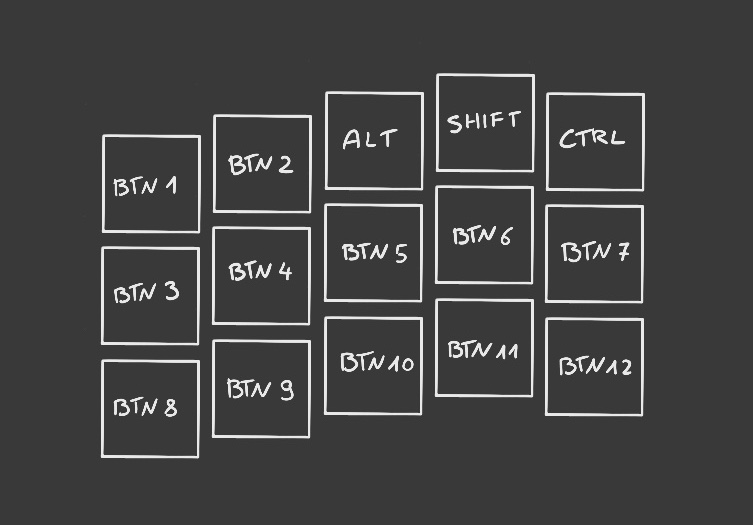
The illustration below shows an early concept for the layout. The goal is to make the layout ergonomical. Each of the keys will be rebindle on the hardware level. The thumb will work on the side surface, and that’s where most of unique features will be placed.
This project seems to be pretty young. That’s a bit misleading because I’ve already spent quite a bit of time on the software. I already have a basic BLE HID device running on the SparkFun Artemis Thing Plus board. There are still some major bugs there but it’s good enough to actually build a prototype.
This is a project that scratches my itch for creating a custom BLE controller. The focus for this design is to help with computer graphics, more precisely working with Blender, ZBrush, etc. The idea is to create a one hand device which remaps all of the necessary keyboard shortcuts into a more intuitive controls.
There are a lot of concepts that repeat in every 3D program. Camera control is one of those concepts. There is always panning, rotating and zooming, but each application has a different set of shortcuts for that. Another concept is a brush. A lot of 3D apps have some sort of a brush and changing its size is something that you do often. In ZBrush I’d like to have this functionality easily accessible. It also doesn’t make sense to be controlled by buttons. In fact a size of a brush maps to an analog control. Unfortunately, since most of the programs have been designed to work with keyboard and mouse, the brush’s size control is quantized, meaning you can have a brush size of 10 or 11, but not anything in between. A controller can’t change how the size of a brush is stored and changed but it can provide an interface that gives more of an analog feel. For that I’d like to try adding a continuous (meaning without detents) encoder to control things like brush’s size or intensity.